
Case Study: Repeatable Pack-Out for a 28-Component Deployable Medical Kit
Case Study: Repeatable Pack-Out for a 28-Component Deployable Medical Kit

Executive Summary
Due to the confidential nature of this program, some technical details, product views, and identifying information have been intentionally withheld, limited, or modified. The information and images included in this case study are presented in a way that preserves the accuracy of the packaging solution while protecting sensitive aspects of the underlying equipment.
A North Carolina-based manufacturer was developing a new deployable medical system containing 28 separate pieces of equipment, cables, accessories, and spare components. The customer initially tested the packaging concept internally using pick-and-pluck foam divided among three cases. We then converted those concepts into three custom 2 lb.-density polyethylene foam prototypes, making several layout improvements while preserving the customer’s general equipment groupings.
The three-case system protected and organized the equipment, but it created an operational weakness. An end user lost one of the cases, and because all three were required to form one complete system, the remaining two cases could no longer support the full use of the kit. The customer decided that all 28 components needed to travel together in one controlled pack-out.
Vol Case redesigned the system around a single Pelican 1780. The completed case weighed approximately 85 lbs. when loaded and used both the base and lid as organized storage. Every component had a fixed location. Repeated-use equipment was positioned in the base, spare parts were secured in the lid, and the remaining layout was organized by component type and sequence of use.
The first consolidated 3D model was completed within one week of the request. After the customer identified additional components and sent the full equipment set to Vol Case, we cut and assembled the physical prototype within ten days. Changes identified during customer review were incorporated the same day.
Once approved, the pack-out became the production standard. The customer ordered 20 units, followed approximately two months later by another 20, and then 25 more roughly two months after that. Each order was completed within one month. All 65 units used the same approved layout, with no design changes between runs and no need for the customer to resend the physical equipment.
To date, there have been no reported fitment problems, equipment damage, or recurrence of the separated-case issue that affected the original configuration.
Project Snapshot
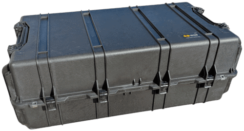
- Program type: Rugged hard-case pack-out with custom foam interior
-
Equipment category: Deployable medical system
- Project stage: Internal concept to full production
-
Turnaround: 1 month
- Transport modes: Freight, vehicle, air, sea, and off-road vehicle
-
Number of components: 28 components
-
Case used: Pelican 1780 Protector
- Foam used: 2 lb. PE foam
-
Lid retention: Fifteen 1″ wide elastic nylon straps
-
Production quantity: Three orders of 20, 20, and 25
-
Repeatability result: 65 units across three production runs with zero design changes
-
Loaded kit weight: 85 lbs.
- Outcome: Three production runs completed with the same approved layout and no reported fitment or damage issues
The Challenge
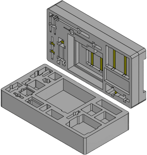
The customer was developing a brand-new product and needed packaging before the final pack-out method had been fully established. Their internal team began by arranging the equipment in pick-and-pluck foam across three separate cases.
That approach gave the customer an initial way to test equipment groupings and determine which components needed to travel together. It did not, however, provide the fit control or repeatability of a CNC-cut foam system.
Because the customer had worked with Vol Case previously, they brought the three layouts to us for the next stage of development. Those three custom prototypes helped establish the individual equipment pockets.
We created three custom 2 lb. PE foam prototypes based on the original concepts. The general organization was preserved, but the pocket locations and fitment were modified where needed to improve the layouts.
The larger problem did not become clear until later.
An end user lost one of the three cases. Although the remaining two cases and their contents were still intact, the equipment was designed to function as one complete system. Without the components in the missing case, the other two could no longer support the full intended use of the kit.
The customer therefore needed more than another revision to the existing foam. They needed to change the packaging architecture from three dependent cases into one complete packaging system.
Key Requirements
To succeed, the packaging solution needed to meet several requirements at the same time:
Keep the complete system together
All 28 components needed to travel in one case. The packaging could no longer depend on three separate containers remaining together through shipment, storage, deployment, and repacking.
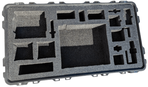
Establish a fixed location for every component
Each item needed one defined position. The pack-out had to remain visually understandable so operators could identify where components belonged and determine whether anything was missing.
Preserve the customer’s operational grouping
The customer had already established useful groupings during the earlier three-case development stage. The consolidated layout needed to carry that logic forward rather than reorganizing the kit only around whichever arrangement was easiest to manufacture.
Use the smallest practical case
The customer did not want to solve the consolidation problem by moving into an unnecessarily large container. The layout needed to fit the complete system into the smallest practical hard case while preserving usable access to the equipment.
Protect equipment in both the lid and base
Using the lid created additional capacity, but it also introduced the possibility of cables or spare components moving downward and contacting the equipment stored in the base. The lid and base therefore had to be designed as one interior system.
Support future identical builds
The approved prototype needed to become a repeatable production design. Later units had to preserve the same pocket geometry, component locations, strap arrangement, and assembly method even when orders were placed months apart.
Pass military packaging requirements
The military end user expected to transport the equipment in almost any environment. Therefore, the completed pack-out needed to pass several vibration and environmental tests to ensure it complied with the military packaging requirements. All testing was done by an independent third-party lab.
The Packaging Solution
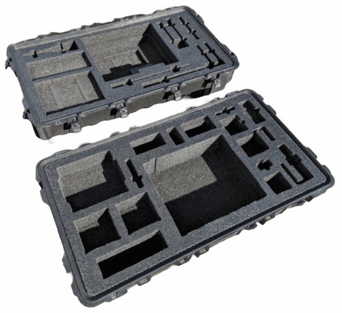
We developed the consolidated pack-out around a Pelican 1780 with custom CNC-routed 2 lb. PE foam in both the base and lid.
The objective was to identify the smallest practical case that could hold all 28 components. One large primary unit positioned near the center of the case drove much of the overall design. Its size, orientation, and required removal method affected nearly every surrounding pocket.
The Pelican 1780 was useful because its deep lid allowed the upper portion of the central unit to extend into the lid volume when the case was closed. The unit could sit partly within the base foam while remaining sufficiently exposed when the case was opened.
Normally, a large component like this might receive dedicated hand-access cavities around its sides. In this layout, however, large hand slots would have consumed space needed for the other 27 components. Allowing the upper section of the unit to remain exposed gave the operator a practical gripping area without sacrificing as much foam footprint.
The base foam consisted of two layers totaling 7.25 inches thick. The lid also used two layers, totaling 7.5 inches thick. Both foam sets measured approximately 41 inches long by 21.5 inches wide. The finished case weighed approximately 85 lbs. when fully loaded.
Fixed Component Locations and Operational Layout
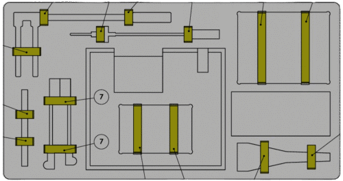
Every component in the final kit had a fixed location.
The first level of organization was based on access frequency. Equipment expected to be used repeatedly was placed in the base, where it could be reached directly when the case was opened. Spare parts and less frequently accessed items were placed in the lid.
Within those two main zones, components were further organized by sequence of use and component type. Items used near one another during operation were kept together where practical. Similar cables, accessories, and related parts were also grouped so the pack-out would be easy to understand.
This retained the useful operational logic from the original three-case arrangement while consolidating the equipment into one case.
Pocket shapes were made visually distinct enough that it was generally clear which part belonged in each location.
That organization supported several practical functions:
- Missing equipment was easier to notice
-
The complete kit could be checked before transport
- Operators could identify where each component belonged
-
Equipment could be returned to the same location after use
- Different production units could be unpacked and repacked using the same logic
For a technical kit with 28 components, the foam layout effectively became part of the operating system. Instead of relying entirely on memory, users could use the pocket geometry and component groupings as a visual pack-out guide.
The controlled layout also improved presentation. When opened, the case showed a complete system with an intentional equipment arrangement rather than a collection of items placed into general-purpose cavities.
Using the Lid as Controlled Storage
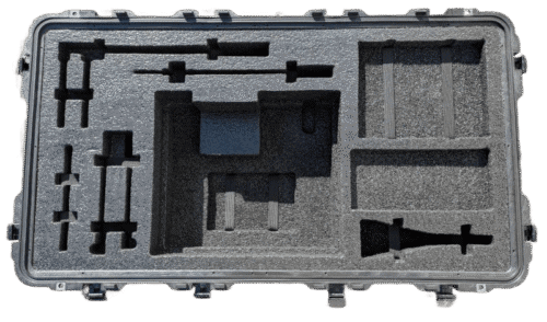
The lid was necessary to fit the complete kit into one case, but it could not be treated as miscellaneous open storage.
Spare components and lower-frequency items were prioritized for lid placement. This kept the repeatedly used equipment in the base while still using the available lid volume efficiently.
Many of the lid-mounted components were cables or other flexible items. Those parts created a specific retention challenge.
Using too few straps could allow a cable or accessory to sag into the base when the case was open or move downward toward the primary equipment when the case was closed. Using too many straps would make routine removal and repacking unnecessarily slow.
The final design used fifteen 1″ wide elastic nylon straps in the lid. Combined, each case required approximately 27 linear feet of strapping.
The straps were not all cut to one generic length. Individual lengths were programmed based on the component and retention point. Vol Case used an automatic strap cutter to reproduce those specified lengths during production. This allowed us to produce the correct strap lengths across production runs quickly and consistently.
The customer reviewed the completed prototype to determine whether the strap arrangement provided the right balance between retention and accessibility. The approved layout used enough restraint to control the lid-mounted parts without requiring operators to release an excessive number of straps each time the kit was used.
Manufacturing the Two-Layer Lid Consistently
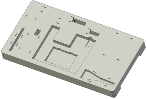
The two-layer lid design created a manufacturing issue that had to be controlled before the pack-out could become repeatable.
The elastic straps needed to pass through the foam assembly and remain free to stretch. Because the lid consisted of two bonded foam layers, adhesive had to be applied between those layers during assembly.
If adhesive was applied across a strap path, the strap could become bonded to the foam. Even a small amount of misplaced glue could prevent the elastic from moving freely or create inconsistent strap performance from one case to another.
Relying on an assembler to estimate the no-glue areas would have introduced unnecessary variation. Instead, the CNC program placed reference marks on the rear foam layer showing where adhesive could not be applied.
Those marks created controlled glue-exclusion zones for the straps. Once the upper foam layer was installed, the production markings were hidden inside the completed foam set.
This addressed both function and appearance. The straps remained free to stretch, the adhesive process could be repeated using the same guidance on every unit, and the visible surface of the finished lid remained clean.
The same CNC reference geometry was preserved for later production runs, allowing the lid assembly method to remain consistent even when orders were separated by several months.
Fitment, Clearance, and Foam Durability
Fitting 28 components into one case required more than placing cavities close together. The lid and base had to be evaluated together in the closed position.
Additional depth for scratch-sensitive equipment
Several heavier components in the base had surfaces that could not be scratched. Because equipment was also stored in the lid, there was a risk that the two groups could contact one another if the clearances were too tight.
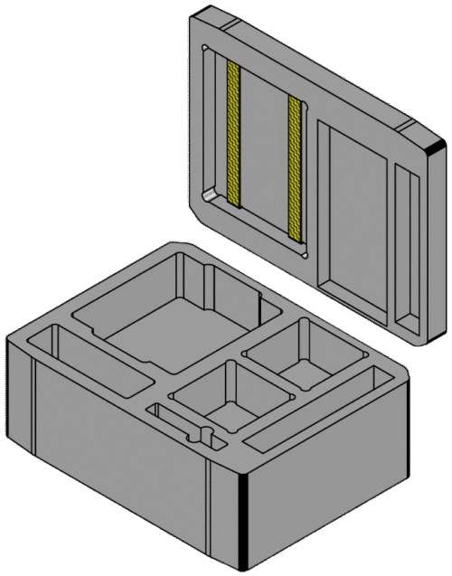
The pockets for these base components were cut an additional 1/4 inch deep. This lowered the equipment within the base foam and created more vertical separation from the items secured in the lid.
The additional depth was intentional clearance, not loose fitment. The components still had dedicated pockets, but their upper surfaces were kept farther away from the lid-mounted equipment when the case was closed.
Material continuity from earlier prototypes
The consolidated pack-out continued to use 2 lb. PE foam, matching the material used in the earlier three-case prototypes. By the time the system was consolidated, many of the individual component pockets had already been evaluated during the first prototype stage.
The primary design challenge was therefore no longer determining how each individual item should fit. It was determining how to nest and orient all 28 proven component locations within one case while maintaining access, grouping, clearance, and manufacturability.
Dog-bone reliefs for sharp equipment corners
Several parts had sharp external corners. A sharp corner repeatedly inserted into a matching square foam pocket can concentrate load at the inside corner of the cutout. Over time, that can cut into the foam or cause localized wear.
To reduce that problem, selected pockets in both the lid and base used dog-bone corner reliefs. The relief cuts created space for the equipment’s hard corners so those corners would not continually load the same small section of foam.
This helped make insertion easier and reduced the likelihood of the sharp corners damaging the pocket through repeated packing and unpacking.
Anticipated transport environment
The customer expected the kits to move through freight, vehicle, air, sea, and off-road vehicle transport. Therefore, testing was needed to ensure that the equipment and packaging could handle the rigors of all transportation modes.
The consolidated pack-out passed the third-party testing required by the program, including vibration testing representative of the anticipated transport conditions. To date, there are no customer reports of equipment damage in the field.
Design Development and Customer Collaboration
This was not an emergency rush project, but the design and prototype work still moved quickly.
The customer first approached Vol Case with its three internally developed pick-and-pluck layouts. We converted those concepts into three custom-foam prototypes and made minor layout modifications based on fitment and manufacturing considerations.
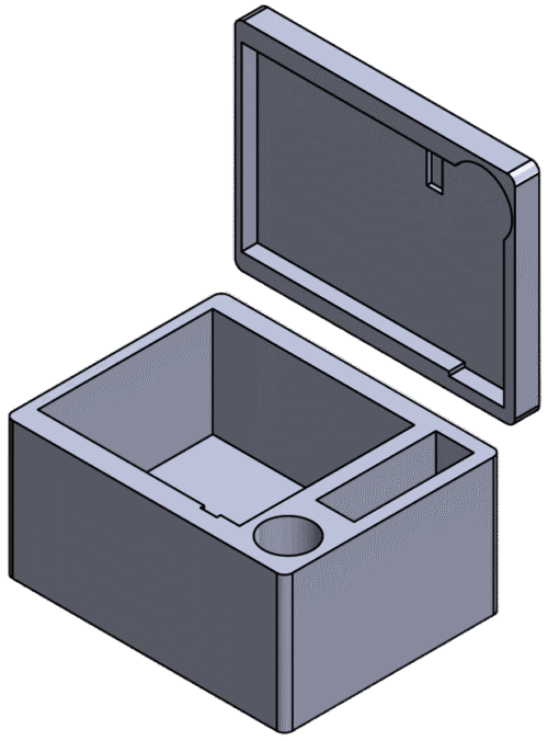
After the lost-case incident, the customer requested a consolidated design.
We completed the first 3D model for the one-case system within one week of that request and shared it with the customer for review. During the review, the customer realized that additional components needed to be included beyond those represented in the initial consolidated design.
The customer then shipped the complete equipment set to Vol Case.
Using the physical parts, we revised the layout, cut a new foam prototype, and loaded all 28 components into the case. The physical prototype was completed within ten days of receiving the equipment.
The customer reviewed the complete pack-out, including the component organization, access, lid retention, and overall fitment. Changes identified during that review were incorporated the same day.
The full development sequence included:
- Customer-created pick-and-pluck layouts across three cases
-
Three Vol Case custom 2 lb. PE foam prototypes with layout modifications
- Initial 3D concept for a single consolidated case
-
Updated equipment list after additional components were identified
-
Revised design based on the complete physical equipment set
- Physical consolidated prototype
-
Customer review and same-day final changes
- Approved production design
This progression allowed the customer to validate the packaging in stages. The early three-case prototypes established individual fitment. The consolidated prototype then established the complete operational layout that would be used for production.
Outcome
After the consolidated prototype was approved, the customer placed an initial production order for 20 units.
Approximately two months later, they ordered another 20. Roughly two months after that, they placed a third order for 25 more units.
Each production order was completed within one month. In total, Vol Case manufactured 65 cases using the approved consolidated design.
There were zero design changes between the three production orders. The same component locations, pocket geometry, foam construction, strap arrangement, and assembly logic were used across all three runs.
The customer did not need to resend the physical equipment for the second or third production orders. Those units were produced from the retained design and manufacturing information.
To date, there have been:
- No reported fitment issues
-
No reported equipment damage
- No requested design changes during the three production runs
-
No reported recurrence of the multi-case separation problem
The absence of follow-on design requests does not by itself prove performance under every possible condition. It does, however, provide practical evidence that the approved layout remained acceptable to the customer through multiple orders and continued use.
The repeat orders also showed that the project had moved beyond a one-off prototype. The customer was able to order future kits using the same established packaging standard rather than restarting the design and fitment process each time.
Prototype-to-Repeatability
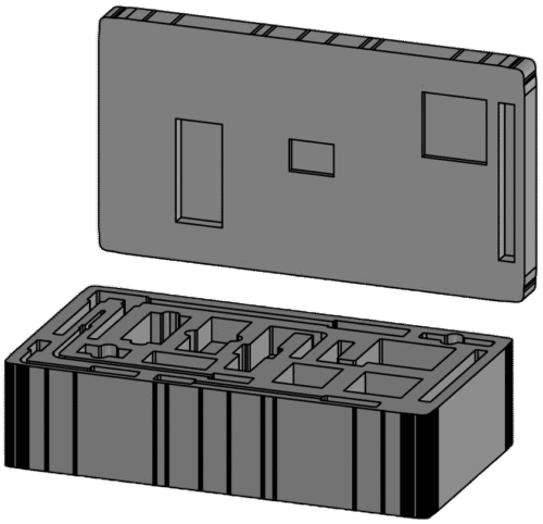
The defining result of this project was the transition from a physical prototype into a controlled, repeatable packaging system.
The complete equipment set was needed to establish and verify the final consolidated layout. Once the prototype was approved, however, future units could be produced without requiring the customer to send the 28 components back to Vol Case.
The production information retained for the program included:
- The approved 3D model
-
Foam drawings and part information
- CNC cutting programs
-
Production machine code
- Programmed strap lengths
-
Strap placement locations
- CNC glue-exclusion reference marks
-
Bills of materials
- Assembly instructions
-
Relevant quality-control dimensions
- Inspection requirements
No physical master sample was retained. Instead, the approved digital design and production records became the manufacturing reference.
That distinction mattered when the second and third orders arrived months later. The later foam sets were not recreated by measuring equipment again or visually copying a previous case. They were manufactured using the same approved geometry and controlled production information as the first run.
The automatic strap cutter reproduced the specified individual strap lengths. The CNC programs reproduced the same pocket geometry and glue-exclusion markings. The assembly records preserved the layer construction and strap locations. Quality-control information provided defined points for checking the finished units.
This created repeatability on two levels.
From a manufacturing standpoint, Vol Case could reproduce the same case-and-foam solution across separate production orders.
From an operational standpoint, every end user received the same pack-out logic:
- The same 28 fixed component locations
-
The same repeatedly used equipment in the base
- The same spare-component storage in the lid
-
The same grouping by component type and sequence of use
- The same strap arrangement
-
The same access and clearance features
That consistency is what turns one approved custom case into a repeatable pack-out system. A unit built several months later can open the same way, contain the same equipment arrangement, and support the same unpacking and repacking process as the first production unit.
Conclusion
The original three-case system demonstrated that individual cases can protect and organize equipment while still leaving the overall kit vulnerable to separation. When every container is required for the system to function, losing one case can affect the usefulness of the entire pack-out.
Consolidating the equipment successfully required more than selecting a larger hard case. The case platform, base foam, lid foam, equipment groupings, strap retention, closed-case clearance, pocket geometry, and production records all had to be developed as one system.
For deployable medical, communications, robotics, test, and other multi-component technical kits, the objective is often not simply to make one set of equipment fit once. The objective is to establish a repeatable pack-out system that can protect the equipment now and preserve the same fixed layout for future units.
In this project, one approved 28-component prototype became 65 production units across three separate orders. The physical parts were not required again, the design did not change between production runs, and the same pack-out method was carried from the first unit into every later build.
About Vol Case
Volunteer Case & Container is the oldest custom crate and case manufacturer in the East TN area. Founded over 30 years ago, all of our protective packaging solutions are still designed and assembled at our facility in Oak Ridge, TN. We specialize in custom wood crates, ATA cases, wood or plastic containers, injection molded cases, and waterjet or CNC cut foam inserts. Our customers span a variety of industries including nuclear, government, aerospace, military, medical, R&D, and more. Our team has experience designing and building everything from huge wood crating for 70,000+ lbs machinery to small injection molded cases for key-sized objects. Whatever your needs, our team works on quick turnaround times to provide you with high quality protective packaging. Contact us today for a free quote.
Contact Us
Whether you need one wood crate or hundreds of ATA cases, we’d love the chance to earn your business. All of our designs and quotes are done for free without any purchase required. We are able to work off dimensions/CAD files that you provide to us or we can visit your facility to take measurements of the equipment.
(865) 481-3801
sales@volcase.com
328 Warehouse Rd. Oak Ridge, TN 37830